How to Choose the Best Carbide Inserts for Cutting Aluminum?
Are you tired of poor surface finishes and constant tool failures when machining aluminum? I’ve seen countless machinists waste thousands of dollars on the wrong inserts, struggling with built-up edge and premature tool wear.
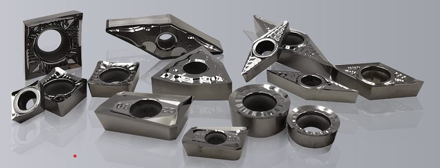
The best carbide inserts for cutting aluminum have sharp cutting edges, highly polished rake faces, positive rake angles (10-20°), and aluminum-specific chip breakers. Uncoated carbide works well for general purposes, while PCD inserts offer superior performance for high-volume production or demanding applications.
After 15 years in the carbide insert manufacturing business, I’ve helped hundreds of customers solve their aluminum machining problems. The right insert selection can dramatically improve your productivity, reduce costs, and eliminate quality issues. Let me share what I’ve learned about choosing the perfect insert for your aluminum cutting needs.
Why Is Aluminum Considered a “Difficult” Material to Machine?
Have you experienced frustrating built-up edge or poor surface finish when cutting aluminum? Many machinists don’t realize that despite its softness, aluminum requires specialized tooling approaches that differ greatly from other metals.
Aluminum is challenging to machine because it’s soft yet sticky, causing it to adhere to cutting edges (built-up edge), has high thermal expansion, and produces long, stringy chips that can tangle. These properties demand specific insert geometries with sharp cutting edges, polished surfaces, and proper chip control features.
One of my customers in the aerospace industry was experiencing terrible surface finish issues on their aluminum components. They were using the same carbide inserts they used for steel, not realizing that aluminum requires a completely different approach. After switching to the proper aluminum-specific inserts, their scrap rate dropped by 85% and productivity increased by 30%.
Understanding Aluminum’s Unique Properties
To select the right insert for aluminum, you need to understand what makes this material unique from a machining perspective. Aluminum has several properties that directly impact how it interacts with cutting tools:
High Thermal Expansion
Aluminum expands significantly when heated, about twice as much as steel. This means that as cutting temperatures increase during machining, the workpiece dimensions can change. This property creates several challenges:
- Dimensional accuracy issues: As the part heats up, dimensions can change, making tight tolerances difficult to maintain.
- Increased friction: Thermal expansion can cause the material to grip the tool more tightly, generating even more heat.
- Residual stress: Uneven heating and cooling can create internal stresses that may cause parts to warp after machining.
Low Melting Point
Aluminum melts at relatively low temperatures (660°C/1220°F) compared to steel (1370°C/2500°F). This means:
- Risk of material smearing: During cutting, localized heat can cause the aluminum to become plastic and smear rather than cut cleanly.
- Built-up edge formation: Partially melted aluminum can adhere to the cutting edge, changing the effective geometry of the tool.
- Heat management importance: Effective cooling becomes critical to prevent these issues.
High Adhesion Tendency
Aluminum has a strong tendency to stick to cutting tools, particularly those not designed for aluminum. This leads to:
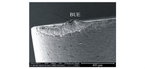
- Built-up edge (BUE): The most common problem in aluminum machining, where aluminum particles weld themselves to the cutting edge.
- Deteriorating surface finish: As BUE builds and then breaks off, it leaves poor surface quality on the workpiece.
- Unpredictable tool life: Tools can fail prematurely due to the changing effective geometry caused by material buildup.
| Aluminum Property | Impact on Machining | Insert Solution |
| High thermal expansion | Dimensional accuracy issues | Sharp cutting edges to reduce heat |
| Low melting point | Material smearing and adhesion | Polished rake faces, proper cooling |
| High adhesion tendency | Built-up edge formation | PCD inserts or specialized coatings |
| Soft but abrasive | Gummy cutting behavior | Positive rake angles, sharp edges |
| Chip formation | Long, stringy chips | Aluminum-specific chip breakers |
The Cost of Using the Wrong Inserts
Using standard inserts not designed for aluminum can lead to significant hidden costs:
- Increased scrap rates: Poor surface finish and dimensional issues lead to rejected parts.
- Frequent tool changes: Premature wear and built-up edge formation require more frequent tool replacement.
- Reduced productivity: Lower cutting speeds and feeds are necessary to compensate for unsuitable tooling.
- Higher energy consumption: Dull or improper tools increase cutting forces and power requirements.
I once worked with a manufacturer who was replacing inserts every 30 minutes when cutting aluminum extrusions. After switching to aluminum-specific inserts, their tool life extended to over 4 hours per edge, reducing tooling costs by 75%.
What Are the Key Features of Aluminum-Specific Carbide Inserts?
Are you confused by the countless insert options available for aluminum machining? Many manufacturers make expensive mistakes by selecting inserts based solely on price or familiarity rather than performance features.
Aluminum-specific inserts feature sharp cutting edges with minimal or no edge preparation, highly polished rake faces (Ra<0.2μm), large positive rake angles (10-20°), optimized clearance angles (12-20°), and specialized chip breakers designed for soft materials. These features work together to minimize built-up edge and produce excellent surface finishes.
I received a call from a frustrated production manager who had tried five different “general purpose” inserts for their aluminum parts, all with disappointing results. After I explained the critical features needed for aluminum machining, they selected the right insert and immediately saw a 50% reduction in cycle time and vastly improved surface quality.
Critical Geometry Elements for Aluminum Cutting
The geometry of an insert plays a decisive role in its performance when machining aluminum. These key elements work together to ensure clean cutting and chip control:
Rake Angle Optimization
The rake angle is perhaps the most critical geometric feature for aluminum cutting tools:
- High positive rake angles: Aluminum-specific inserts typically feature rake angles between 10° and 20°.
- Cutting force reduction: Higher positive angles reduce cutting forces, generating less heat and friction.
- Chip flow improvement: Steeper rake angles help lift and curl the chip away from the workpiece.
In my experience, increasing the rake angle from a standard 5° to a more aluminum-appropriate 15° can reduce cutting forces by up to 30% and significantly improve surface finish.
Edge Preparation
Unlike inserts for harder materials that often feature edge honing or chamfers, aluminum-specific inserts have different requirements:
- Sharp cutting edges: Minimal or no edge preparation preserves sharpness.
- Clean cutting action: Sharp edges slice through aluminum rather than pushing it, reducing heat and deformation.
- Reduced built-up edge: Sharp edges minimize the material adhesion that leads to BUE.
One automotive component manufacturer I worked with solved persistent quality issues simply by switching from inserts with a 25μm edge hone to ones with a sharp edge, eliminating the built-up edge that was causing their problems.
Surface Finish and Coatings
The surface treatment of the insert itself has a major impact on aluminum machining performance:
- Highly polished surfaces: Rake faces should be polished to a mirror finish (Ra<0.2μm).
- Reduced aluminum adhesion: Smooth surfaces minimize the mechanical “hooks” where aluminum can adhere.
- Specialized coatings: When coatings are used, they should be specifically designed for non-ferrous materials.
| Feature | Standard Insert | Aluminum-Specific Insert | Benefit |
| Rake Angle | 0° to 10° | 10° to 20° positive | Lower cutting forces, better chip evacuation |
| Edge Preparation | 15-30μm hone | Sharp edge (0-5μm) | Cleaner cutting, reduced BUE |
| Surface Finish | Ra 0.4-0.8μm | Ra <0.2μm (polished) | Minimizes aluminum adhesion |
| Clearance Angle | 7° to 11° | 12° to 20° | Reduces rubbing and heat generation |
| Chip Breaker | General purpose | Aluminum-specific | Controls long, stringy chips |
Chip Breaker Designs for Aluminum
Chip control is a particular challenge when machining aluminum due to its tendency to form long, stringy chips that can tangle and damage both tools and workpieces:
- Open chip breakers: Aluminum-specific designs feature wider, more open geometries.
- Lower obstructions: Smaller “bumps” or obstacles in the chip flow path.
- Longer chip flow distance: Allows chips to naturally curl before breaking.
When I visit machine shops struggling with aluminum chip control, I often find they’re using inserts with aggressive chip breakers designed for steel. Switching to aluminum-specific chip breakers can eliminate tangling issues and improve overall process reliability.
Which Insert Material Is Best: Uncoated Carbide, Coated Carbide, or PCD?
Are you overwhelmed by conflicting recommendations about insert materials for aluminum? I’ve seen many shops waste money on expensive PCD inserts when they don’t need them or struggle with inappropriate coated inserts that actually worsen aluminum machining problems.
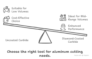
For aluminum cutting, uncoated carbide works well for general purposes and lower volumes, diamond-coated carbide offers a good middle ground, while PCD (polycrystalline diamond) provides superior performance for high-volume or demanding applications. The best choice depends on your production volume, surface finish requirements, and specific aluminum alloy.
In our testing lab, we regularly benchmark different insert materials on various aluminum alloys. Recently, we demonstrated to a customer that while PCD inserts cost 8 times more than uncoated carbide, they lasted 12 times longer and allowed cutting speeds to increase by 200%. For their high-volume production, the investment in PCD made economic sense, saving them over $40,000 annually in tooling and productivity costs.
Uncoated Carbide: The Versatile Baseline
Uncoated carbide inserts remain a popular choice for many aluminum machining applications:
Strengths of Uncoated Carbide
- Cost-effectiveness: The lowest initial investment of all options.
- Sharp edges: Can be manufactured with very sharp cutting edges ideal for aluminum.
- Good thermal conductivity: Helps dissipate heat from the cutting zone.
- Versatility: Can be used for multiple aluminum alloys and operations.
Limitations of Uncoated Carbide
- Shorter tool life: Wears more quickly than premium options like PCD.
- Lower possible cutting speeds: Maximum productivity is limited.
- More frequent replacements: Higher labor costs for tool changes.
I recommend uncoated carbide for:
- Low to medium volume production
- Job shops with varying requirements
- Applications where tool cost is a primary concern
- Situations requiring frequent geometry changes
Diamond-Coated Carbide: The Middle-Ground Solution
Diamond-coated carbide inserts offer enhanced performance while keeping costs lower than solid PCD:
Advantages of Diamond Coatings
- Extended tool life: 3-5 times longer than uncoated carbide.
- Higher cutting speeds: Can increase productivity significantly.
- Excellent surface finish: The diamond coating provides a very smooth cutting action.
- Moderate cost increase: More affordable than solid PCD.
Challenges with Diamond Coatings
- Coating adhesion issues: The coating can delaminate, especially at edges or with improper use.
- Limited resharpening: Once the coating wears through, the advantage is lost.
- Thickness limitations: The coating changes the cutting edge geometry slightly.
One of my electronics industry customers was experiencing inconsistent results with uncoated carbide when machining aluminum housings. By switching to diamond-coated inserts, they increased tool life by 4.5 times while also improving surface finish consistency. The moderate cost increase was easily justified by the performance gains.
PCD (Polycrystalline Diamond): The Premium Choice
For high-volume or demanding aluminum applications, PCD inserts offer unmatched performance:
PCD Performance Benefits
- Exceptional tool life: 8-12 times longer than uncoated carbide.
- Maximum cutting speeds: Often 2-3 times faster than carbide options.
- Superior surface finish: Consistently excellent results even over long production runs.
- Thermal stability: Maintains performance even at elevated temperatures.
PCD Considerations
- High initial cost: 5-8 times more expensive than uncoated carbide.
- Limited geometry options: Not available in all insert shapes and styles.
- Specialized equipment: May require specific holders or machine capabilities.
- Brittleness: More susceptible to chipping from interruptions or impacts.
| Material | Relative Cost | Relative Tool Life | Max Cutting Speed | Best For | ROI Break-Even |
| Uncoated Carbide | 1x | 1x | 500-1,000 SFM | Low volume, versatility | Immediate |
| Diamond-Coated | 2-3x | 3-5x | 1,000-2,000 SFM | Medium production | 2-3 production runs |
| PCD | 5-8x | 8-12x | 2,000-5,000 SFM | High volume, precision | 4-6 production runs |
| CVD Diamond | 10-15x | 15-20x | 3,000-6,000 SFM | Ultra-high volume | 8-10 production runs |
Material Selection Decision Framework
To help you select the right material for your specific application, I’ve developed this decision-making framework based on production volume and requirements:
- For prototype or low-volume production (less than 100 parts):
- Uncoated carbide is typically the most cost-effective choice
- Focus on proper geometry rather than material
- For medium-volume production (100-1,000 parts):
- Diamond-coated carbide offers a good balance of performance and cost
- Consider PCD only for high-precision requirements
- For high-volume production (over 1,000 parts):
- PCD typically provides the lowest cost-per-part despite higher initial investment
- The productivity gains often outweigh the material cost
- For abrasive aluminum alloys (high silicon content >8%):
- PCD is almost always the best choice regardless of volume
- Tool life with carbide options is significantly reduced in these materials
How Do I Select the Right Insert Shape for Different Aluminum Machining Operations?
Are you using the same insert shape for all your aluminum operations? This common mistake costs shops thousands in lost productivity and poor part quality. Different operations require specific insert shapes for optimal performance.
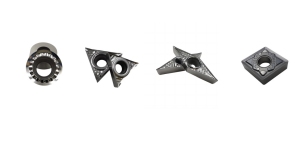
For aluminum machining, round inserts excel in face milling and high-feed applications, triangle inserts work well for general turning and finishing, square inserts are ideal for shoulder milling, and diamond (rhombic) inserts provide excellent results in profiling and contour machining. The best shape depends on your specific operation and required part features.
I recently visited a customer who was struggling with aluminum face milling. They were using square inserts and experiencing chatter, poor surface finish, and short tool life. After switching to round inserts with the same grade and coating, their surface finish improved dramatically, and they doubled their feed rate while extending tool life by 60%.
Round Inserts: Superior for Face Milling Aluminum
Round inserts have several advantages that make them particularly well-suited for aluminum face milling applications:
Benefits of Round Inserts for Aluminum
- Progressive engagement: The curved cutting edge enters the cut gradually, reducing impact forces.
- Variable effective lead angle: Adapts to different cutting conditions automatically.
- Maximum edge strength: No vulnerable corners means less chance of chipping.
- Excellent surface finish: The continuous radius leaves a smooth surface.
- Higher feed capability: Can often run at 2-3 times the feed rate of other shapes.
Application Recommendations
Round inserts perform exceptionally well in:
- Face milling aluminum plates and blocks
- High-feed roughing operations
- Interrupted cutting situations
- Applications where surface finish is critical
In one automotive plant, replacing traditional square inserts with round inserts in their aluminum block face milling operation increased productivity by 40% while improving surface finish quality and reducing tool change frequency.
Triangle Inserts: Versatile for General Turning
Triangular inserts offer a good balance of versatility, economy, and performance for many aluminum turning operations:
Advantages in Aluminum Turning
- Sharp cutting points: The 60° included angle creates naturally sharp corners.
- Multiple cutting edges: Three usable points (six on double-sided inserts) for economy.
- Good accessibility: Can reach into corners and detailed features.
- Lower cutting forces: Requires less power than other shapes.
Best Applications for Triangle Inserts
Triangular inserts excel in:
- General-purpose aluminum turning
- Finishing passes on aluminum parts
- Detail work where access is important
- Machines with limited horsepower
One of my aerospace industry customers reduced their tooling costs by 35% by standardizing on triangular inserts for their aluminum turning operations, without sacrificing performance or quality.
| Insert Shape | Strengths in Aluminum | Best Applications | Limitations |
| Round | Highest edge strength, best surface finish | Face milling, high-feed roughing | Limited access to shoulders/corners |
| Triangle | Good detail access, economy, low cutting forces | General turning, finishing, detail work | Less edge strength than round |
| Square | Strong corners, good for 90° shoulders | Shoulder milling, facing, step cutting | Less versatility in profiling |
| Diamond (55°) | Excellent profiling capability, good access | Contour machining, profile turning | Fewer cutting edges than triangle |
| Diamond (80°) | Combines turning and facing ability | Multi-directional machining | Less accessible in tight spaces |
Diamond (Rhombic) Inserts: Ideal for Profiling
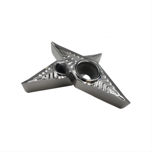
Diamond-shaped inserts come in different included angles (commonly 55°, 80°, and 35°), each offering specific advantages for aluminum machining:
55° Diamond Inserts
- Versatile approach angles: Work well for both turning and light profiling.
- Good chip control: The geometry naturally directs chips away from the workpiece.
- Reach capability: Can access more detailed features than larger-angle diamonds.
80° Diamond Inserts
- Greater edge strength: The larger included angle provides more support.
- Multi-directional capability: Excellent for combined turning and facing operations.
- Stability in cut: Less prone to vibration than more acute geometries.
Application Guidelines
For aluminum profiling operations:
- Use 55° diamond inserts for general contour machining
- Select 80° diamond inserts when more edge strength is needed
- Consider 35° diamond inserts for fine detail work
Special Considerations for Insert Selection
Beyond the basic shape, several other factors should influence your insert selection for aluminum:
- Nose radius: Larger radii provide better surface finish but limit access to details
- Insert size: Smaller inserts allow more detailed work but with less edge strength
- Mounting security: Ensure the clamping method securely holds the insert without deformation
- Effective cutting edge length: Match to your required depth of cut
I helped one electronics manufacturer select the perfect insert shape for their complex aluminum housing components. By analyzing their specific requirements and selecting diamond inserts with the optimal included angle and nose radius, they reduced cycle time by 35% while improving dimensional accuracy.
What Cutting Parameters Should I Use with Carbide Inserts for Aluminum?
Are you running your aluminum machining operations too conservatively? Most shops I visit are using less than half the potential cutting speed and feed rate their inserts can handle, leaving significant productivity gains on the table.
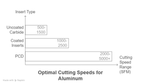
For aluminum with carbide inserts, optimal cutting speeds range from 500-1,500 SFM for uncoated carbide, 1,000-2,500 SFM for coated inserts, and 2,000-5,000+ SFM for PCD. Feed rates should be aggressive (0.005-0.020 ipr for turning) to prevent rubbing. Depth of cut is less critical but should be at least twice the nose radius.
One manufacturing facility I consulted with was running their aluminum milling operation at just 800 SFM because that’s what they used for steel. After testing and optimization, we safely increased their cutting speed to 2,400 SFM and tripled the feed rate. The result? Their cycle time dropped from 17 minutes to just under 5 minutes per part, with no negative impact on tool life or quality.
Cutting Speed (Vc) Optimization
Cutting speed is perhaps the most critical parameter to optimize when machining aluminum:
Speed Guidelines by Insert Material
- Uncoated Carbide:
- Starting range: 500-1,000 SFM (150-300 m/min)
- Advanced applications: Up to 1,500 SFM (450 m/min)
- Lower speeds for gummy alloys (2000 series)
- Coated Carbide (aluminum-specific coatings):
- Starting range: 1,000-1,800 SFM (300-550 m/min)
- Advanced applications: Up to 2,500 SFM (750 m/min)
- Diamond-coated: 1,500-3,000 SFM (450-900 m/min)
- PCD Inserts:
- Starting range: 2,000-3,500 SFM (600-1,050 m/min)
- Advanced applications: Up to 5,000+ SFM (1,500+ m/min)
- Can exceed 10,000 SFM in specialized applications
The “Too Slow” Problem
Running too slow when cutting aluminum often creates more problems than running too fast:
- Built-up edge formation: Slower speeds increase the likelihood of aluminum adhesion
- Heat concentration: Without sufficient speed, heat concentrates in a smaller area
- Poor chip evacuation: Slower speeds can result in chip packing and re-cutting
- Reduced productivity: Obvious impact on cycle time and throughput
I’ve seen numerous cases where increasing cutting speed actually improved tool life – counter to what many machinists expect. In one case, doubling the cutting speed from 1,000 to 2,000 SFM reduced built-up edge so significantly that tool life improved by 40%.
Feed Rate (f) Considerations
Feed rate selection is equally important when machining aluminum:
Recommended Feed Rates by Operation
- Turning Operations:
- Roughing: 0.008-0.020 ipr (0.2-0.5 mm/rev)
- Finishing: 0.004-0.012 ipr (0.1-0.3 mm/rev)
- With PCD inserts: Can increase by 30-50%
- Milling Operations:
- High-feed face milling: 0.015-0.030 ipr/tooth (0.4-0.8 mm/tooth)
- Profile milling: 0.006-0.015 ipr/tooth (0.15-0.4 mm/tooth)
- Slotting: 0.004-0.012 ipr/tooth (0.1-0.3 mm/tooth)
Avoiding the “Too Light” Feed Problem
Insufficient feed rates when cutting aluminum create specific issues:
- Rubbing instead of cutting: Light feeds cause the edge to rub rather than shear
- Increased heat generation: Rubbing generates more heat than proper cutting
- Work hardening: Surface may harden, making subsequent passes more difficult
- Reduced tool life: Counterintuitively, too light feeds often reduce insert life
| Parameter | Common Mistake | Optimal Approach | Result |
| Cutting Speed | Too slow (300-500 SFM) | Properly fast (1,500-3,000 SFM) | Less BUE, better surface finish |
| Feed Rate | Too light (0.002-0.004 ipr) | Appropriately aggressive (0.008-0.015 ipr) | Proper cutting instead of rubbing |
| Depth of Cut | Too shallow (<2x nose radius) | Adequate (>2x nose radius) | Better chip formation, less vibration |
| Engagement | Full-width cuts | Optimized width of cut (40-60%) | Better chip evacuation, less heat |
Depth of Cut (ap) and Width of Cut (ae)
While speed and feed are often the focus, depth and width of cut also play important roles:
Depth of Cut Guidelines
- Minimum threshold: At least twice the nose radius to ensure proper shearing
- Roughing operations: As deep as machine rigidity and power allow
- Finishing passes: 0.020-0.040″ (0.5-1.0mm) typically sufficient
Width of Cut Considerations in Milling
- Optimal engagement: 40-60% of cutter diameter for best chip evacuation
- Full-width cuts: Require reduced feed rates to manage chip load
- Light radial cuts: May need increased cutting speed to maintain proper chip formation
Parameter Adjustment by Alloy Type
Different aluminum alloys require parameter adjustments:
- Pure aluminum and 1000 series: Can run fastest, with minimal adjustments
- 2000 series (Al-Cu): Reduce speeds by 10-15% due to increased gumminess
- 6000 series (Al-Mg-Si): Standard parameters work well, excellent machinability
- 7000 series (Al-Zn): Standard to slightly reduced speed (5-10%) depending on hardness
- Cast alloys with silicon (319, 356, etc.): Reduce speed by 20-30% for low silicon, use PCD for high silicon content
I developed a custom parameter optimization program for one aerospace customer machining various aluminum alloys. By tailoring cutting parameters to each specific alloy and feature, they reduced their overall machining time by 43% while improving surface finish consistency.
What Cooling Strategies Maximize Insert Life When Cutting Aluminum?
Are you struggling with premature insert failure and poor surface finish despite using quality aluminum-specific inserts? The problem might be your cooling strategy, an often-overlooked aspect of aluminum machining that can make or break your results.
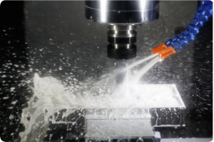
Effective cooling strategies for aluminum include high-pressure coolant (500+ PSI) directed at the cutting edge, flood cooling with proper nozzle positioning, and minimum quantity lubrication (MQL) with aluminum-specific formulations. Proper cooling prevents built-up edge, extends insert life, and improves surface finish.
I visited a shop that was replacing inserts every 20 minutes when machining large aluminum components. Their coolant was poorly directed, with nozzles aimed generally at the cutting zone rather than precisely at the cutting edge. After repositioning the nozzles and increasing pressure, tool life extended to over 90 minutes, and surface finish improved dramatically.
High-Pressure Coolant: The Game Changer
High-pressure coolant delivery has revolutionized aluminum machining in recent years:
Benefits of High-Pressure Cooling
- Superior chip evacuation: Forces chips away from the cutting zone immediately
- Enhanced cooling effect: Penetrates the boundary layer for more effective heat removal
- Built-up edge prevention: Continuously cleans the cutting edge during machining
- Extended insert life: Typically increases tool life by 50-100% compared to conventional cooling
Implementation Considerations
To effectively implement high-pressure cooling for aluminum:
- Pressure requirements: 500-1,000 PSI (35-70 bar) is typically optimal
- Nozzle positioning: Direct precisely at the cutting edge-chip interface
- Nozzle diameter: Smaller diameter (0.5-1.0mm) creates more focused jet
- Flow rate: 1-2 gallons per minute per nozzle is typically sufficient
One aerospace customer implemented high-pressure coolant for their aluminum structural components and saw tool life increase from 45 minutes to over 3 hours per edge, while also increasing cutting speed by 30%.
Conventional Flood Cooling: Optimizing What You Have
Not every shop has high-pressure capability, but conventional flood cooling can still be highly effective when properly implemented:
Maximizing Conventional Cooling Effectiveness
- Volume over pressure: With conventional cooling, abundant flow is key
- Multiple nozzle approach: Use several nozzles to cover all cutting areas
- Nozzle positioning: Aim directly at the cutting edge, not just the general area
- Coolant maintenance: Regular concentration checks and filtration are critical
Common Coolant Mistakes to Avoid
- Insufficient flow: Too little coolant can be worse than none at all
- Poor concentration management: Incorrect mix ratios reduce effectiveness
- Contamination: Tramp oil and debris significantly reduce cooling efficiency
- Nozzle neglect: Clogged or misaligned nozzles render cooling ineffective
| Cooling Method | Pressure Range | Best For | Limitations | Tool Life Impact |
| High-Pressure | 500-1,000+ PSI | High-speed machining, difficult alloys | Equipment cost, mist control | +50-100% |
| Conventional Flood | 50-100 PSI | General-purpose aluminum machining | Less effective at high speeds | Baseline |
| MQL | N/A (mist) | Environmental concerns, certain operations | Not suitable for all applications | +20-40% |
| Dry Cutting | N/A | Not recommended for most aluminum cutting | Very limited applications | -50-70% |
Minimum Quantity Lubrication (MQL): The Environmental Option
MQL provides an alternative approach that some shops prefer for environmental or specific application reasons:
MQL Benefits for Aluminum
- Reduced environmental impact: Minimal fluid consumption and disposal
- Cleaner parts: Less cleanup required after machining
- Better visibility: Clear view of the cutting operation
- Effective lubrication: Can be highly effective with proper application
MQL Implementation for Aluminum
For effective MQL with aluminum:
- Aluminum-specific formulations: Use lubricants designed for non-ferrous materials
- Proper delivery system: Internal delivery through the tool is highly preferable
- Application rate: Typically 5-50 ml/hour depending on operation size
- Combined approaches: Some applications benefit from MQL plus cold air
Coolant Selection for Aluminum
The type of coolant used can significantly impact aluminum machining performance:
- Semi-synthetic coolants: Often the best balance for aluminum machining
- Synthetic coolants: Can be effective but may have less lubricity
- Soluble oils: Good lubricity but may cause staining on some alloys
- Aluminum-specific additives: Look for formulations with specific aluminum enhancers
I worked with one medical device manufacturer to select the optimal coolant formulation for their high-precision aluminum components. By switching to an aluminum-specific semi-synthetic coolant and implementing proper concentration management, they reduced surface finish variation by 65% and virtually eliminated the staining issues they had been experiencing.
How Can I Troubleshoot and Solve Common Aluminum Machining Problems?
Are you constantly battling with poor surface finish, premature tool wear, or dimensional issues when machining aluminum? Many shops waste valuable time and materials by treating symptoms rather than identifying and addressing root causes.
Most aluminum machining problems stem from built-up edge formation, improper chip control, or thermal issues. Troubleshooting should focus on checking insert geometry (ensure sharp edges and proper rake angles), optimizing cutting parameters (typically increasing speed), improving cooling application, and selecting aluminum-specific inserts.
A customer called me in a panic about scrapping dozens of expensive aluminum aerospace components due to poor surface finish. After a systematic troubleshooting approach, we identified that their coolant concentration had dropped to just 3% (instead of the required 8%), causing built-up edge and surface smearing. After correcting the concentration and switching to a more appropriate insert geometry, the problem was completely resolved.
Diagnosing Built-Up Edge (BUE) Issues
Built-up edge is the most common and problematic issue when machining aluminum:
Identifying BUE Problems
Look for these tell-tale signs:
- Dull, shiny deposits on the cutting edge of the insert
- Poor surface finish
Conclusion
Selecting the right carbide inserts for aluminum machining is crucial for productivity, quality, and cost-effectiveness. Focus on sharp edges, positive rake angles